


Installing Pogo Pin spring - loaded pins correctly is crucial for ensuring their proper functionality and long - term reliability in electronic devices. The installation process can vary depending on the type of Pogo Pin and the application requirements, but generally follows a set of standard procedures.
1. Vertical Mounting
Vertical mounting is one of the most common installation methods. In this approach, the Pogo Pin is inserted vertically into a pre - drilled hole on the printed circuit board (PCB). This method offers several advantages. It provides a stable and secure connection, as the pin is directly soldered to the PCB. The vertical orientation also allows for easy automated assembly processes. Automated soldering techniques, such as wave soldering or reflow soldering, can be used to ensure consistent quality across multiple units. The Pogo Pin’s spring mechanism can compensate for minor misalignment between the mating components, which is particularly important in environments prone to mechanical shock or vibration. To install a Pogo Pin vertically, first, ensure that the PCB hole has the correct diameter to fit the Pogo Pin snugly. Clean the hole and the Pogo Pin to remove any contaminants. Then, insert the Pogo Pin into the hole and apply heat (using a soldering iron or in a soldering oven) to melt the solder and create a strong electrical and mechanical bond. After soldering, it is advisable to perform a visual inspection to check for any signs of poor soldering, such as cold joints or excessive solder.
2. Right - Angle (Horizontal) Mounting
Right - angle or horizontal mounting is suitable for applications where space efficiency is a concern or where there are height restrictions, such as in slim electronic devices or wearable devices. In this method, the spring - loaded Pogo Pin connector extends horizontally from the PCB. The right - angle design simplifies the mating process as the pins are aligned with the corresponding receptacles at a specific angle, reducing the insertion force and minimizing wear on both the connector and the mating surface. To install a right - angle Pogo Pin, start by preparing the PCB with the appropriate pads or traces for the horizontal connection. The Pogo Pin is then soldered to these pads. Special care should be taken to ensure proper alignment during soldering to prevent misalignment that could lead to poor electrical contact. After soldering, the connector should be tested to ensure that it functions correctly. This may involve applying a test voltage or current to check for continuity and proper electrical performance.
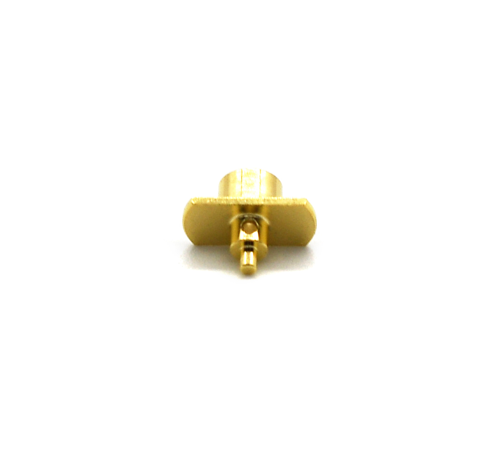
3. Housing with Legs Mounting
Integrating Pogo Pins within a housing that includes legs provides improved stability and alignment during operation. The legs of the housing help maintain proper alignment, even in the presence of shock or vibrations, ensuring that the electrical connection remains intact. This mounting option is particularly useful for applications that require frequent mating cycles, as it reduces wear on both the Pogo Pins and the PCB. The housing also protects the pins from environmental factors such as dust and moisture, which can degrade performance over time. To install Pogo Pins in a housing with legs, first, insert the Pogo Pins into the designated slots or holes in the housing. Secure the Pogo Pins in place, which may involve using adhesives or mechanical fasteners depending on the housing design. Then, mount the housing to the PCB using the legs. The legs can be soldered or screwed to the PCB, depending on the application requirements. After installation, test the connection to ensure that the Pogo Pins are functioning correctly and that the housing provides the intended protection.
4. Combination Mounting
Combination mounting techniques combine the features of different mounting methods to create versatile, interconnected solutions. For example, a combination approach might involve using vertical Pogo Pins housed within a casing that allows them to pivot slightly during mating. This flexibility is ideal in applications where precise alignment cannot always be guaranteed due to manufacturing tolerances or environmental factors. To install Pogo Pins using combination mounting, carefully follow the installation instructions provided by the manufacturer, as the process can be more complex than single - method installations. Ensure that all components are properly assembled and that the different mounting features work together as intended. Test the connection thoroughly to verify its performance under different conditions.
5. Cable - Mounted Installation
Cable - mounted Pogo Pins are attached via flexible cables with solder cups at their ends. This setup allows the pins to connect to various components without being fixed in place, making them suitable for applications that require mobility or dynamic connections. To install cable - mounted Pogo Pins, first, strip the ends of the cable to expose the conductors. Then, insert the conductors into the solder cups of the Pogo Pins and apply heat to solder them in place. Ensure that the soldering is secure to prevent any electrical discontinuities. After soldering, the cable - mounted Pogo Pins can be connected to the desired components, such as a mobile device’s charging port or a sensor module.
In all installation methods, it is important to follow proper safety procedures, use appropriate tools, and ensure that the installation environment is clean and free from contaminants to achieve optimal performance and reliability of the Pogo Pin spring - loaded pins.
Read recommendations:
Purchase price of Pogo Pin Connector


159-2067-7287 Mr. Wan

0769-86006029

No. 5, Zhenrong Road, Wusha, Chang'an Town, Dongguan City
 Whatapp
CopyRight © 2024 Dongguan Yongtan New Energy Co., Ltd. All Rights Reserved


 CN
CN
 Home >